Proximity Sensors
     Operating Principles
     Inductive
     Capacitive
     Magnetic
     Photoelectric
     Connector Cord Sets
     Value Line Proximity
     Sensors

Counters

     Totalizing
     Preset
     Length Measuring
     Mechanical
     Multifunction

Timers

Timers
     Hour Meters
     Elapse Time
     Preset
     Multifunction

Controls
     Sensor Power Supplies
     Timing Controls
     Rotation Controls


Battery powered LCD electronic counter special
Battery powered LCD counter at a great price. $34.95 each

High operating temperature inductive sensors
120°C / 248°F


OPERATING PRINCIPLES FOR CAPACITIVE PROXIMITY SENSORS


Capacitive proximity sensors are used for non-contact detection of metallic objects & nonmetallic objects (liquid, plastic, wooden materials and so on). Capacitive proximity sensors use the variation of capacitance between the sensor and the object being detected. When the object is at a preset distance from the sensitive side of the sensor, an electronic circuit inside the sensor begins to oscillate. The rise or the fall of such oscillation is identified by a threshold circuit that drives an amplifier for the operation of an external load. A screw placed on the backside of the sensor allows regulation of the operating distance. This sensitivity regulation is useful in applications, such as detection of full containers and non-detection of empty containers. The operating distance of the sensor depends on the actuator shape and size and is strictly linked to the nature of the material (Table 1).


Table 1. Sensitivity when different materials are present. Sn = operating distance.
Metal ~ 1 x Sn
Water ~ 1 x Sn
Plastic ~ 0.5 x Sn
Glass ~ 0.5 x Sn
Wood ~ 0.4 x Sn

Outputs:

DC Voltage

4 wire DC: These amplified D.C. sensors contain an output amplifier. They are supplied as 4 wire with complementary outputs (NO + NC) in the types NPN and PNP. Standard version include protected against short circuit, protected against polarity and peaks created by the disconnection of inductive loads. They are compatible with P.L.C. Units

AC/DC Voltage

These are two-wire sensors that contain a mosfet output amplifier that functions in both A.C. and D.C. In this system a residual current flows through the load even when in the open state and a voltage drop occurs to the sensor when it is in the closed state. Attention must be paid to the minimum switching current, residual current and voltage drop when selecting low consumption relays or high impedance electronic controls to be used with these sensors. All AC/DC capacitive sensors are short circuit protected (up to 50 Vdc and 250 Vac). They are also protected against transient voltage coming from the power supply or generated by the load. They are compatible with P.L.C. units.


AC Voltage

2 wire AC: These are two-wire sensors that contain a thyristor output amplifier. In this system a residual current flows through the load even when in the open state and a voltage drop occurs to the sensor when it is in the closed state. Attention must be paid to the minimum switching current, residual current and voltage drop when selecting low consumption relays or high impedance electronic controls to be used with these sensors. They are compatible with P.L.C. Units

Definitions:

NO (normally open): A switch output that is open prohibiting current flow when an actuator is not present and closes allowing current flow when an actuator is present.

NC (normally closed): A switch output that is closed allowing current flow when no actuator is present and opens prohibiting current flow when an actuator is present.

NPN Output: Transistor output that switches the common or negative voltage to the load. The load is connected between the positive supply and the output. Current flows from the load through the output to ground when the switch output is on. Also known as current sinking or negative switching.

PNP Output: Transistor output that switches the positive voltage to the load. The load is connected between output and common. Current flows from the device's output, through the load to ground when the switch output is on. Also known as current sourcing or positive switching.

Operating Distance (Sn): The maximum distance from the sensor to a square piece of Iron (Fe 37), 1mm thick with side's = to the diameter of the sensing face, that will trigger a change in the output of the sensor. Distance will decrease for other materials and shapes. Tests are performed at 20ºC with a constant voltage supply. This distance does include a ± 10% manufacturing tolerance.

Power Supply: The supply voltage range that sensor will operate at.

Max Switching Current: The amount of continuous current allowed to flow through the sensor without causing damage to the sensor. It is given as a maximum value.

Min Switching Current: It is the minimum current value, which should flow through the sensor in order to guarantee operation.

Max Peak Current: The Max peak current indicates the maximum current value that the sensor can bear in a limited period of time.

Residual Current: The current, which flows through the sensor when it is in the open state.

Power Drain: The amount of current required to operate a sensor.

Voltage Drop: The voltage drop across a sensor when driving the maximum load.

Short Circuit Protection: Protection against damage to a sensor if the load becomes shorted.

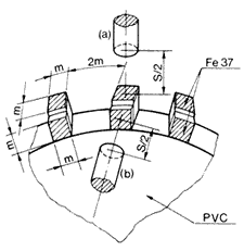
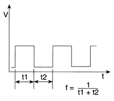
Operating Frequency: The maximum number of on/off cycles that the device is capable of in one second. According to EN 50010, this parameter is measured by the dynamic method shown in fig. 1 with the sensor in position (a) and (b). S is the operating distance and m is the diameter of the sensor. The frequency is given by the formula in fig. 2.

Repeatability (%Sn): The variation between any values of operating distance measured in an 8 hour period at a temperature between is 15ºC -30ºC and a supply voltage with a <= 5% deviation.

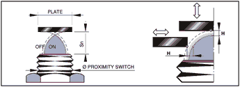
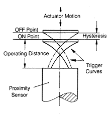
Hysteresis (%Sn): The distance between the "switching on" point of the actuator approach and the "switching off" point of the actuator retreat. This distance reduces false triggering. Its value is given as a percent of the operating distance or a distance. See Fig. 3

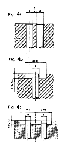
Flush Mounting: For side by side mounting of flush mount models refer to Fig. 4a. Non-flush mount models can be embedded in metal according to Fig. 4b. for side by side refer to fig. 4c. Sn = operating distance.

Protection Degree: Enclosure degree of protection according to IEC (International Electrotechnical Commission) is as follows:
IP 65: Dust tight. Protection against water jets.
IP 67: Dust tight. Protection against the effects of immersion

Fig. 1


Fig. 2


Fig.3


Home            Specials            News            About Us            Literature Request            Contact Us
Copyright © 1998-2020 Fargo Controls Inc. All Rights Reserved.